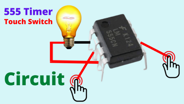
If you’re looking to build a simple touch switch circuit, the 555 timer IC is a great choice. It’s versatile, easy to use, and requires minimal components. In this post, we’ll guide you step-by-step on how to create a touch-activated switch using the popular 555 timer IC.
What is a 555 Timer?
The 555 timer IC is a widely used integrated circuit for generating precise time delays or oscillations. It has three modes of operation: astable, monostable, and bistable. In this project, we will use it in bistable mode, where it will act as a flip-flop to toggle an output (on/off) with each touch.
Components You’ll Need
- 555 Timer IC
- 2N2222 NPN Transistor or any general-purpose NPN transistor
- 1MΩ resistor
- 10μF capacitor
- Touch plates (can be made using conductive material like copper or aluminum foil)
- 10kΩ resistor
- LED (for indicating output)
- Power supply (5V or 9V battery)
- Breadboard and jumper wires
Circuit Diagram
Before diving into the construction, here’s a quick look at the layout of the touch switch circuit. Below is a basic description of how components will be connected:
- 555 Timer Pin Configuration:
- Pin 1: Ground
- Pin 2: Trigger (connected to the touch plate)
- Pin 3: Output (connected to the LED)
- Pin 4: Reset (connected to VCC)
- Pin 5: Control Voltage (optional; usually grounded via a capacitor)
- Pin 6: Threshold (connected to Pin 2)
- Pin 7: Discharge (not connected)
- Pin 8: VCC (Power Supply)
- Touch Plate Setup:
- Connect one touch plate to Pin 2 of the 555 Timer.
- Connect the other touch plate to the ground (GND).
- Output:
- An LED is connected between Pin 3 and ground through a 1kΩ resistor to indicate when the touch switch is activated.
- Transistor Driver:
- Use an NPN transistor to drive heavier loads if needed.
Step-by-Step Instructions
1. Assemble the Components
Begin by placing your 555 Timer IC on the breadboard. Make sure the notched side of the IC faces left, so the pins are correctly positioned.
2. Connect the Power
Connect Pin 1 (GND) to the ground rail of the breadboard, and Pin 8 (VCC) to the positive rail, ensuring a 5V or 9V power supply.
3. Set up the Touch Plates
Connect one side of your touch plates (you can use aluminum foil or a small piece of copper) to Pin 2 of the 555 Timer. The other side should connect directly to ground. These plates will act as the touch-sensitive input for the circuit.
4. Output Configuration
Connect Pin 3 of the 555 Timer (the output pin) to the longer leg of an LED. Attach a 1kΩ resistor between the LED and ground. This LED will light up when the touch switch is activated.
5. Add the Resistor and Capacitor
- Attach a 1MΩ resistor between Pin 6 and Pin 2 of the 555 timer.
- Add a 10μF capacitor between Pin 6 and ground. This will help stabilize the output.
6. Connect the Transistor (Optional for High Power Output)
If you want to control a higher power load, such as a motor or light bulb, you can add a transistor driver.
- Connect the base of the 2N2222 transistor to Pin 3 of the 555 timer through a 10kΩ resistor.
- The collector should connect to the load, while the emitter connects to the ground.
How It Works
The circuit works by detecting a small change in capacitance when you touch the plates. This change triggers the 555 timer, causing the output to toggle between HIGH (on) and LOW (off).
- Touch Activation: When you touch the plate, the capacitance on Pin 2 changes. This small voltage difference is enough to trigger the 555 timer.
- Bistable Mode: The 555 timer remains in either an ON or OFF state until the next touch occurs, which toggles the state.
- LED Indication: The LED turns on or off based on the output state of the 555 timer, showing the status of the switch.
The 555 Timer is presently the foremost wide used physics part. many sorts of comes is finished it. If you recognize a way to make out well then completely different electronic circuits will use it. Plus, you’ll be obtaining eliminate muddle you don’t want. Timer IC is associate degree eight pin IC. nowadays i will be able to show you the way you’ll be able to build slightly switch with 555 timer IC. it’s terribly straightforward to form slightly switch with 555 timer IC. By creating this switch you’ll be able to flip any load on and off. you need to use a driver circuit with it to run a load of a lot of amperes or AC load. Below is that the pin diagram of this 555 timer IC.

Now I have shown below the pin diagram or connection diagram of how you can make a touch switch with this 555timer IC.

Touch will be created if you connect according to this connection diagram. Here I have shown with only one LED. If you want to run AC load you need to use driver circuit.
Applications of the 555 Timer Touch Switch
This touch switch circuit can be used in a variety of applications:
- Touch-sensitive lamps
- Home automation projects
- Security systems
- Interactive toys
Conclusion
The 555 timer touch switch circuit is an excellent beginner project to understand the basics of touch-sensitive inputs and how a 555 timer IC works. With just a few components, you can create a functional touch-activated switch that can control an LED or other devices.
If you’re planning to expand the circuit, consider experimenting with different sensors, or even using this as a basis for a more advanced touch control system.

