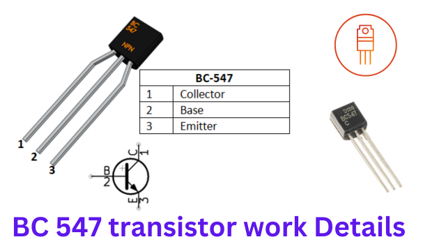
The BC 547 transistor is a commonly used NPN bipolar junction transistor (BJT) in electronics projects. It is widely utilized for amplification and switching applications due to its low cost, availability, and reliable performance. Here’s a detailed overview of its working principles and characteristics:
Key Specifications
- Type: NPN BJT
- Maximum Collector-Emitter Voltage (Vce): 45V
- Maximum Collector Current (Ic): 100mA
- Maximum Collector-Base Voltage (Vcb): 50V
- Maximum Emitter-Base Voltage (Veb): 6V
- Power Dissipation (Ptot): 500mW
- DC Current Gain (hFE): 110 to 800 (varies with model, e.g., BC547A, BC547B, BC547C)
- Transition Frequency (ft): 300 MHz
Pin Configuration
- Collector (C)
- Base (B)
- Emitter (E)
Working Principle
1. Amplification
- Base-Emitter Junction: When a small current is applied to the base terminal, it allows a larger current to flow from the collector to the emitter. This is because the transistor is a current-controlled device.
- Current Gain: The ratio of the collector current (Ic) to the base current (Ib) is called current gain (hFE). For the BC547, this can range from 110 to 800.
- Operating Regions: In active mode, the transistor acts as an amplifier. The base-emitter junction is forward-biased, and the collector-base junction is reverse-biased.
2. Switching
- Cutoff Region: When the base current is zero, the transistor is in the cutoff region, and no current flows through the collector-emitter path. The transistor acts like an open switch.
- Saturation Region: When the base current is sufficient to saturate the transistor, the collector-emitter path is fully conductive, acting like a closed switch. The voltage drop across the collector-emitter is minimal (typically 0.1-0.3V).
Applications(BC 547 transistor)
- Switching Circuits: Used in digital circuits to switch loads such as LEDs, relays, and other devices.
- Amplifiers: Used in audio amplification, signal amplification, and other analog circuits.
- Oscillator Circuits: Utilized in various oscillator designs for generating signals.
Example Circuit: Basic Switch
Here’s an example of a basic switching circuit using a BC547 transistor:
- Components:
- BC547 Transistor
- Resistor (1kΩ)
- LED
- Power Supply (e.g., 9V battery)
- Connections:
- Emitter: Connect to the negative terminal of the power supply.
- Collector: Connect to one end of the LED. The other end of the LED connects to the positive terminal of the power supply.
- Base: Connect to the positive terminal of the power supply through the 1kΩ resistor.
- Operation:
- When a small current flows into the base through the resistor, the transistor turns on, allowing current to flow from the collector to the emitter.
- The LED lights up, indicating that the transistor is conducting.
Detailed Working Explanation
- Forward Biasing the Base-Emitter Junction: Applying a positive voltage to the base relative to the emitter causes the base-emitter junction to become forward-biased. This reduces the potential barrier and allows electrons to flow from the emitter to the base.
- Current Amplification: The small base current controls the larger collector current. The transistor operates in the active region, where the collector current is proportional to the base current.
- Switching Behavior: In switching applications, the transistor operates in cutoff (no base current, no collector current) and saturation (sufficient base current, maximum collector current) regions. This allows it to function effectively as an electronic switch.
See More:
Related search’s:
BC547 Transistor
BC547 transistor price
Transistor BC547 datasheet
BC547 transistor Circuit diagram
BC547 transistor projects
BC547 transistor voltage
BC547 transistor pinout
BC547 transistor as a switch
GPS location tracker: See NOW

